FUEL-06, Throttle Position Switch - Information, Troubleshooting, Replacement, and Adjustment
Acrobat Printable Version
Introduction
A faulty throttle position switch (TPS) can result in a number of poor running problems. Because they can result in such a large number of problems, faulty switches often go undiagnosed. The other thing that makes TPS problems difficult to diagnose is that they quite often only appear when the engine is warmed up (throttle position switch warmed up).
The following lists some of the symptoms that MAY indicate a problem with the throttle position switch:
Poor idle - particularly a high idle condition
Engine cuts out to an idle condition during acceleration
Poor power at various RPMs (various throttle positions)
Surging idle
Misfire
Stumble during acceleration
Intermittent boost problems (turbocharged cars)
Tools
Multimeter
Test leads
Phillips screwdriver
Testing
NOTE
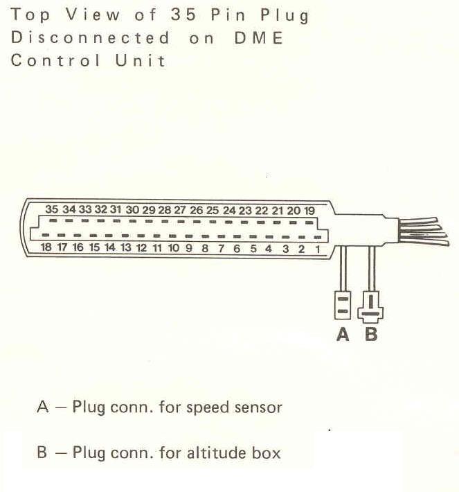
On 1985.5 and newer cars, the DME control unit is located behind the kick panel in the passenger's footwell. For pre-1985.5 cars, the DME is located under the dash on the driver's side.
For 8V Normally Aspirated cars:
Disconnect the electrical connector for the DME.
Connect an ohmmeter between terminal 2 on the DME wiring harness plug and ground. This will test the idle speed contact. With the throttle closed, the ohmmeter should read zero (0) ohms. With the throttle open, the ohmmeter should read infinite (∞). The switch in resistance must occur as soon as the throttle starts to open (approximately 1°).
Connect the ohmmeter between terminal 3 on the DME wiring harness plug and ground. This will test the wide open throttle (WOT) contact. With the throttle closed, the ohmmeter should read infinite (∞). With the throttle wide open the ohmmeter should read zero (0) ohms. The switch in resistance should occur just before the throttle reaches full open.
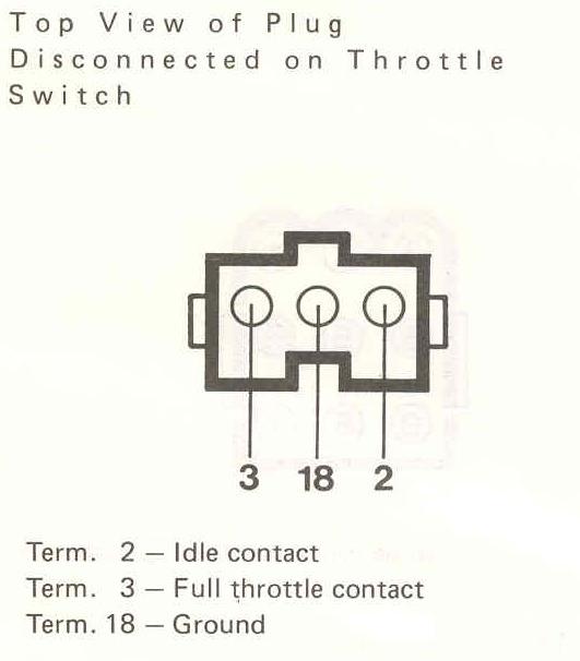
If reading at the DME plug are unsatisfactory, the test should be repeated at the switch. This will require removing the throttle body from the car. The ohmmeter should be connected between the center terminal on the switch (ground) and each of the outer terminals (2 and 3) and resistance values checked as described above.
For 16V Normally Aspirated cars:
NOTE
The 16V N/A cars use the same TPS as the early cars. Pictures of the 16V DME plug will be available in a few days.
Disconnect the electrical connector for the DME.
Connect an ohmmeter between terminals 52 and 24 on the DME wiring harness plug. This will test the idle speed contact. With the throttle closed, the ohmmeter should read 0 - 10 ohms. With the throttle open, the ohmmeter should read infinite (∞). The switch in resistance must occur as soon as the throttle starts to open (approximately 1°).
Connect the ohmmeter between terminals 53 and 24 on the DME wiring harness plug. This will test the wide open throttle (WOT) contact. With the throttle closed, the ohmmeter should read infinite (∞). With the throttle approximately 2/3 open, the ohmmeter should read zero (0) ohms.
If reading at the DME plug are unsatisfactory, the test should be repeated at the switch. This will require removing the throttle body from the car. The ohmmeter should be connected between the center terminal on the switch (ground) and each of the outer terminals (2 and 3) and resistance values checked as described above.
For turbocharged cars:
Disconnect the electrical connector for the DME control unit.
Connect an ohmmeter between terminal 2 on the DME wiring harness plug and ground. This will check the idle contact.
With the throttle closed, the ohmmeter should read between 0 - 10 ohms. With the throttle open, the ohmmeter should read infinite (∞). The switch in resistance must occur as soon as the throttle starts to open (approximately 1°).
Disconnect the electrical connector for the KLR control unit.
Connect an ohmmeter between terminals 22 and 23 on the KLR wiring harness plug. With the throttle closed, the ohmmeter should read between 320 - 670 ohms.
Slowly open the throttle to the wide open throttle (WOT) position. As the throttle opens, the resistance should continuously increase to full open resistance without any breaks. Full open resistance is 2.7 - 4.7 Kohms.
Replacement and Adjustment
Normally Aspirated cars:
Remove the throttle body from the car.
Remove the two Phillips head screws that attach the TPS to the throttle body.
Install the new TPS and insert the mounting screws. Do not tighten the screws until the adjustment is complete.
Hold the throttle in the closed position and turn the TPS until the internal stop is felt and tighten the mounting screws.
Check the adjustment by turning the throttle toward the open position. An audible click should be hear as soon as the throttle starts to open. Slowly close the throttle until it is fully closed. Do not force the throttle closed. Allow it to close under spring pressure only. Just prior to going fully closed, an audible click should again be heard. If the click is not heard, readjust the switch.
Install the throttle body.
Turbocharged cars:
NOTE
On turbocharged cars, the throttle body does not have to be removed from the car. However, the bottom mounting screw for the TPS is extremely difficult to remove and install. So, I always replace the Phillips head screws the 4 mm Allen head bolts. They are much easier to remove and install than the Phillips screws - especially if you have a long ball head Allen tool.
Remove the two Phillips head screws that attach the TPS to the throttle body.
Install the new TPS and insert the mounting screws. Do not tighten the screws until the adjustment is complete.
Hold the throttle in the closed position and turn the TPS until the internal stop is felt and tighten the mounting screws.
Check the adjustment by turning the throttle toward the open position. An audible click should be hear as soon as the throttle starts to open. Slowly close the throttle until it is fully closed. Do not force the throttle closed. Allow it to close under spring pressure only. Just prior to going fully closed, an audible click should again be heard. If the click is not heard, readjust the switch.