Acrobat Printable Version
|
FUEL-16, Troubleshooting Fuel Supply Problems
|
This procedure is used to troubleshooting fuel supply problems including failure of the fuel pump to start during engine cranking.
Labelling on Early 944 (Pre-1985.5) terminal boards may be inconsistent, non-existent, or difficult to read. It may therefore be necessary to determine the terminals to be used for testing by looking at the labels by the stabs on the bottom of the relay.
|
|
| Fuel Pump Fuse | Pre-1985.5 944s - Fuse #2 on Auxiliary Fuse Panel 1985.5 and Newer 944s and 968s - Fuse #34 on Central Electric Panel
|
| Bypass Power to Fuel Pump | Remove Fuel Pump / DME relay and install jumper to bypass the Fuel Pump / DME relay and DME computer and directly power the fuel pump.
If the fuel pump does not start, use an external 12 VDC power source to apply power directly to the fuel pump. If the fuel pump starts, check the wiring from the relay panel to the fuel pump and perform the Fuel Pump / DME Relay Primary Supply Voltage check. If the fuel pump does not start with power supplied directly at the pump, the fuel pump is bad and should be replaced.
|
| Fuel Pump / DME Relay Primary Supply Voltage | Remove the Fuel Pump / DME Relay and check for supply voltage (approximately 12 VDC) from the battery. Insert a male spade connector into the relay board terminal to make checking the voltage easier.
If no voltage is present, the battery is dead or the wire from the battery to the relay panel is broken / disconnected.
|
| Fuel Pump / DME Relay Primary Primary Coil Voltage | Remove the fuel pump / DME relay, turn the ignition switch to the "run" position, and check for approximately 12 VDC at the relay primary coil terminal.
If primary coil voltage is present, turn the ignition key off, install the Fuel Pump / DME relay and proceed to the next test.
|
| Fuel Pump / DME Relay Primary Coil Activation | Disconnect the plug from the DME Computer. Turn the ignition switch to the "ON" position and check for supply voltage (approximately 12 VDC) from the Fuel Pump / DME Relay to the DME computer electrical connector.
|
| For the fuel pump to start and remain running, for the ignition coil to develop secondary voltage, and for the injectors to fire, the DME computer must see an engine start signal or an engine running signal (greater than 200 RPM). When it does, it completes the circuit for the Fuel Pump / DME Relay secondary coil and the fuel pump starts. It also provides a ground or current flow path for the ignition coil primary and secondary coils. As a result, the current flow through the primary coil induces a voltage in the secondary coil. The voltage across the secondary coil is what is seen at the distributor. The engine cranking / running signal also goes to the injector drivers (2) which provide a ground or current flow path for the fuel injectors to open. The injectors are batch fired which means that all four injectors are fired together. On 944s, injectors 1 and 2 are wired together and injectors 3 and 4 are wired together. However, they are all powered from one injector driver inside the DME computer. The engine start signal is normally generated by a combination of voltage from the ignition switch to the starter solenoid and a signal from the reference sensor. However, if the starter solenoid signal is not present, an engine cranking signal can be generated by the combination of the speed sensor and reference sensor signals. If all of the previous tests have been completed satisfactorily, check for cranking signal inputs as described in the following steps.
|
|
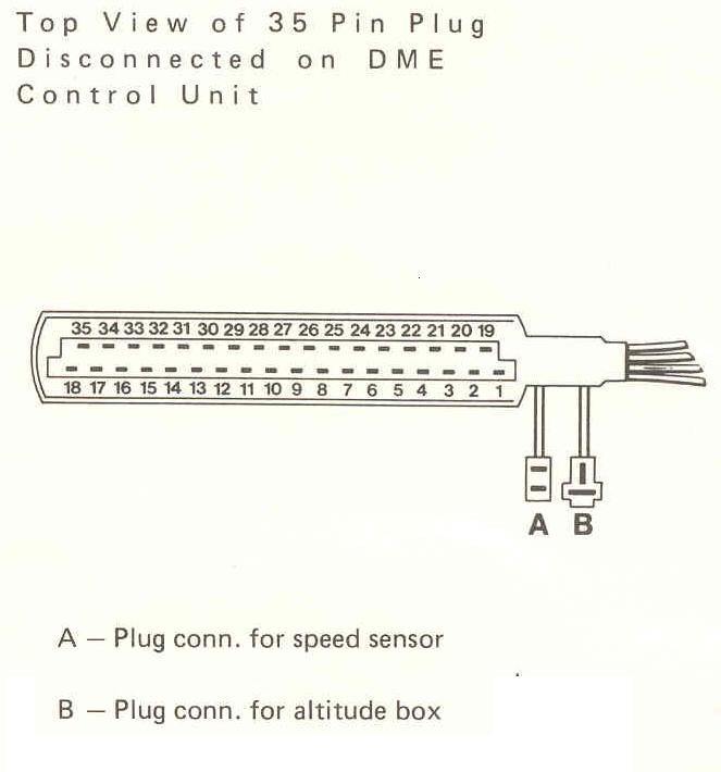
| Speed Sensor | Using an oscilloscope, check the speed sensor output from terminals 8 and 27 on the DME Computer plug. You should get a signal of > 2.5 V. The speed sensor generates an engine speed signal by counting the teeth on the flywheel ring gear. It produces two output pulses for each ring gear tooth. If you don't have an oscilloscope, you can still check the speed sensor by doing a resistance check.
 Check for 600-1600 ohms between terminals 8 and 27 on the sensor connector. Also, check for infinite resistance between terminals 27 and 23.
|
| Reference Sensor | Using an oscilloscope, check the speed sensor output from terminals 25 and 26 on the DME Computer plug. You should get a signal of > 2.0 V. The reference sensor generates an signal relative to engine position at TDC. It produces a single pulse triggered from a bolt cemented in the flywheel. If you don't have an oscilloscope, you can still check the speed sensor by doing a resistance check.
Check for 600-1600 ohms between terminals 25 and 26 on the sensor connector. Also, check for infinite resistance between terminals 26 and 78.
|
| Starter Solenoid Signal | Turn the ignition switch OFF. Disconnect the DME computer plug. Connect a DC voltmeter from terminal 4 on the DME plug to ground. Attempt to crank the vehicle and check for approximately 12 VDC on the voltmeter. If no voltage is present, the ignition switch is bad or the wire from the ignition switch to the DME computer is broken. To check the wire, check the resistance from terminal 50 on the ignition switch electrical plug to terminal 4 on the DME plug. |
| DME computer | The best way to test for a faulty DME computer is to swap it out with a known good DME computer. Now, most of us don't have the luxury of keeping a spare DME computer sitting around on the shelf. However, if you can borrow a DME computer from a friend for testing that's the best test for the DME. Just realize that you can't test an early 944 (pre-1985.5) using a DME computer from a later car or vice versa. They use different injectors. A later DME will not fire early injectors at all. An early DME MAY fire the injectors in a later car but, the current draw will be excessive and you could potentially damage the DMEs injector drivers. Even if you don't damage the injector drivers, they will likely shut down after a few cycles due to the excessive current draw. Other than that, there's actually very little that can be done to check the operation of the DME computer. However, about the only time a 944 DME computer fails is when it's had water intrusion due to a leaking battery tray or if it has bad solder joints which are easily repairable. If you are having trouble getting the car to start and you suspect the DME computer may be the cause, you can sometimes get the car to start by tapping on the outside of the DME computer case with a rubber mallet. If you suspect the DME computer is causing problems, remove the DME computer from the car and inspect for broken solder joints. When you open the DME computer, you'll find two circuit boards mounted face-to-face inside the box. At one end, the two circuit boards are bridge together by a ribbon cable and at the other they're plugged into the main plug terminal. You'll need to separate the two circuit boards, slide one of the boards out of the connector, and lay the boards open (like a book) to inspect the solder joints. For instructions on how to do this, refer to the appropriate sections of DME-02, DME Control Unit Chip Installation (Including KLR Chip for Turbos). When you inspect the DME for bad solder joints, pay particular attention to the solder joints where the ribbon cable joint the two circuit boards. Those tend to be a common source or problems.
|
| Good fuel pressure but no fuel to engine. | Injectors Not Firing | Crank engine while listening for clicking from injectors. Injectors should fire twice for each revolution of the engine.
|
| Good fuel pressure at fuel rail but injectors not firing. | No voltage to injectors. | Perform the following to check for fuel injector supply voltage:
|
| Injector firing signal not present. | Perform checks of Speed Sensor, Reference Sensor, and Starter Solenoid Signal described in the Fuel Pump troubleshooting section.
|
|
| Fuel Pressure too high. | When the fuel pressure runs too high, the fuel injectors draw too much current causing the injector drivers in the DME computer to shut down. Disconnect on fuel injector connector and attempt to crank the engine. If the engine starts, where it would not start with all injector leads connected, the fuel pressure regulator is bad and should be replaced. Disconnecting one fuel injector plug reduces the injector driver current sufficiently to get the injector drivers to fire.
|
|
| Fuel Pressure Low | Clogged Fuel Filter. | If you don't know or can't verify the last time the fuel filter was changed, it's probably a good idea to replace the filter.
|
| Fuel Pump check valve stuck. Not a normal problem with low fuel pressure. Normally associated with fuel system depressurizing after shutdown as the typically stick open. However, if the car hasn't been run for an extended period of time, the check valve can get stuck closed. New fuel pumps normally come with a new check valve.
|
Replace check valve.
|
|
| Fuel Pump bad.
|
Perform fuel pump delivery rate check. (FUEL-04) This assumes that the fuel filter and check valve are good.
|
|
Clark's Garage © 1998