ELECT-18, Sunroof Component Testing


Acrobat Printable Version

Tools

Table of Contents

Testing and/or Replacing the Micro-Switch Between the Sun visors

Introduction

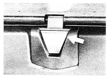
There is a small micro-switch located beneath a triangular shaped cover between the sun visors. This micro-switch serves to stop the sunroof in the fully raised position on early 944 sunroof systems (1982 - February 1986). The mirco-switch is also present on later sunroof systems and functions as a backup to Limit Switch III. This micro-switch is one of the more common failure items on the sunroof. It will prevent the sunroof from operating electrically in the open direction. This means that it can prevent the sunroof from moving from the locked position to the open position OR from the released position to the locked position. However, it should NOT prevent the roof from operating in the closed direction.

Removing and Replacing the Micro-Switch

  1. Release and remove the sunroof hatch. If the sunroof system can not be operated electrically, then manually release the lifting arms using the manual operating instructions in the "Sunroof Operation, Troubleshooting, and Repair" procedure.
  2. Carefully remove the triangular shaped flap from the sunroof mount. Use a small flat tip screwdriver or plastic spatula to pry up gently on either side of the flap. The is snapped into clips on the sunroof mount. The clips on the mount or the tabs on the flap can be easily broken if you pry too hard on the flap.

  3. Once the flap is removed, use a Phillips head screwdriver to remove the retaining screw from the mount and press the mount off of the wind deflector bar.

  4. If the micro-switch is to be replaced, unsolder the wires from switch and install a new switch.

Checking the Sunroof Micro-Switch for Proper Operation

     For the sunroof to operate in the open direction, the micro-switch between the sun visors must be closed and must remain closed. If the micro-switch is open, fails electrically (open), or has a broken wire in the circuit, the sunroof will not open.

  1. Check the operation of the micro-switch as follows:
    1. Remove the sunroof hatch.
    2. Press on the flap covering the sunroof mount (covering the micro-switch).
    3. An audible click should be heard when the flap is depressed. If the click is not heard, remove the flap carefully as described in the previous section.
    4. Depress the micro-switch operating lever and again listen for an audible click.

    5. If an audible click can not be heard or if you still have doubts about whether the microswitch is functioning properly, check the switch electrically.
  2. To check the micro-switch electrically, perform the following:
    1. Lower the sunroof mount (containing the micro-switch) from the roof panel using the directions for removal/replacement in the previous section.
    2. Connect an ohmmeter across the two terminal of the micro-switch. It should read infinite ohms (∞ or OL or Off Scale High depending on what type of meter you use)
    3. Depress the operating lever for the micro-switch. It should read minimum resistance (< 1 ohm).
    4. If the switch does not pass the electrical test, replace it.
    NOTE

    The sunroof micro-switch is operated by a tab on the front of the sunroof hatch. Sometimes that tab can become bent and will not be high enough to depress the micro-switch operator enough to close the switch. If the micro-switch appears to be functioning normally, check it again with the roof installed and closed. If you press upward on the tab at the front of the sunroof and you hear and audible click from the micro-switch, the tab is not bent enough to keep the micro-switch closed. Remove the roof and bent the tab upward slightly until it will close the micro-switch with the roof installed and closed.

Main Sunroof Relay Testing

  1. On early 944s with the small console switch (see picture below), remove the switch from the top of the console using a small flat tip screwdriver or plastic spatula.

  2. On late model 944s with the larger switch, disconnect the sunroof switch plug as follows:
    1. Remove the storage pocket underneath the radio. This can be done by sliding both hands into the pocket, and pressing outward on the sides of the pocket with your hands while pulling the pocket straight out of the console. This will expose two Phillips head screws which you'll need to remove.


    2. Remove the ash tray from the center console by pulling it straight up out of the console and remove the two Phillips head screws at the back of the console.

    3. Lift up on the console insert. You may have to remove the trim piece from around the radio to remove the console insert.
    4. There are two plastic tabs on either side of the console switch which must be released to remove the switch. Use extreme caution when releasing these tabs as they can easily be broken. Nothing will make you more angry than having to replace a perfectly good switch because you've broken off the tabs. The way I release the tabs is to slide small flat tip screwdrivers under both tabs on both sides simultaneously. This releases all four tabs at the same time and the plug should slide off the switch easily.


    NOTE

    On early cars the main sunroof relay checks can be performed on in the back of the switch with it connected to the harness. On the later cars, the checks are performed on the disconnected plug for the sunroof switch.


  3. Check the main sunroof relay output voltages as follows:
    1. On early 944 sunroofs, insert the key into the ignition but, do not turn the switch on. On late 944 sunroofs, turn the ignition to the ACCESSORY position.
    2. Check for approximately 12 VDC at terminal 2 of the sunroof switch / plug.
    3. On early and late 944s, turn the ignition switch to the ON position.
    4. Check for approximately 12 VDC at terminal 1 of the sunroof switch / plug. Also, check that the voltage at terminal 2 of the switch / plug is no longer present.
  4. If the correct output voltages are not present, remove the sunroof main relay. On early 944 (pre-1985.5), the sunroof relay is on the main relay and fuse panel. It is the second relay from the left on the top row of relays. On late model 944s, the sunroof main relay is G18 on the central electric panel. Check for proper supply voltage to the main relay as follows:
    1. On early 944 sunroofs, insert the key into the ignition but, do not turn the switch on. On late 944 sunroofs, turn the ignition to the ACCESSORY position.
    2. Check for approximately 12 VDC at terminal R of the sunroof relay socket.
    3. On early and late 944s, turn the ignition switch to the ON position.
    4. Check for approximately 12 VDC at terminal A and terminal R of the sunroof relay socket.

  5. If the correct supply voltages are present and the correct output voltages are not present, the main sunroof relay is most likely faulty and needs to be replaced.
  6. If the correct output voltages are present, the main sunroof relay is functioning sufficiently to raise and lower the sunroof and to release the lifting arms for sunroof removal.

    NOTE

    There is one remaining check on the main sunroof relay performance. This has to do with the function of the lifting arms to raise from the retracted position to the locked position if the sunroof is installed and the car's speed is sensed to be greater than 5 km/h (3 mph). This can be performed by checking for approximately 12 VDC at terminal 5 of the console switch plug with the car rolling at greater than the required speed. On early 944s (pre-1985.5) this can be done by raising the front of the car and spinning the left front wheel. The 5 km/h is sensed by a hall sensor on the left front wheel. On late 944s, the speed signal comes from the electronic speedometer signal from the hall sensor mounted in the transaxle. So, the car has to be driven or the rear of the car has to be raised and the transaxle rotated to check the voltage.

Limit Switch Testing

Introduction

The sunroof limit switches are a common source of problems with sunroof operation. However, there are fewer problems associated with the limit switches than are often attributed to them. On early 944 sunroofs, the limit switches are located at the back of the sunroof drive cable guide rail. The rail extends from the sunroof motor toward the rear of the car. The limit switches are located on the back side of the rail. The top limit switch is Limit Switch 1 and the bottom is Limit Switch 2. On the late model sunroof system the limit switches are located almost directly above the sunroof motor. The bottom limit switch is Limit Switch I and the top is Limit Switch II.

Below are diagrams showing the early and late model sunroof limit switches and wiring connections and a table showing the limit switch positions and terminal readings for the various sunroof positions.


Wire Connections
Late Model Sunroofs
Early Model Sunroofs
Limit Switch 1 (I) 1 - black/red
2 - green/red
4 - black
3 - black/red
1 - green/red
2 - black
Limit Switch 2 (II) 1 - grey/green
2 - not connected
4 - grey/black
3 - grey/green
1 - not connected
2 - grey/black
Limit Switch III 1 - yellow
2 - yellow/black
4 - not connected
N/A

Late Sunroof Limit Switches
Sunroof Position
Limit Switch 1 (I) Position
Terminal Resistance Readings
Limit Switch 2 (II) Position
Terminal Resistance Readings
Limit Switch III Position
Terminal Resistance Readings
LOCKED
Closed
1-4 <1 ohm
1-2 ∞
Open
1-4 ∞
1-2 <1 ohm
Open
1-4 ∞
1-2 <1 ohm
OPEN
Open
1-4 ∞
1-2 <1 ohm
Open
1-4 ∞
1-2 <1 ohm
Closed
1-4 <1 ohm
1-2 ∞
RELEASED
Closed
1-4 <1 ohm
1-2 ∞
Closed
1-4 <1 ohm
1-2 ∞
Open
1-4 ∞
1-2 <1 ohm

Early Sunroof Limit Switches
Sunroof Position
Limit Switch 1 (I) Position
Terminal Resistance Readings
Limit Switch 2 (II) Position
Terminal Resistance Readings
LOCKED
Closed
2-3 <1 ohm
1-3 ∞
Open
2-3 ∞
1-3 <1 ohm
OPEN
Open
2-3 ∞
1-3 <1 ohm
Open
2-3 ∞
1-3 <1 ohm
RELEASED
Closed
2-3 <1 ohm
1-3 ∞
Closed
2-3 <1 ohm
1-3 ∞

Sunroof Console Switch

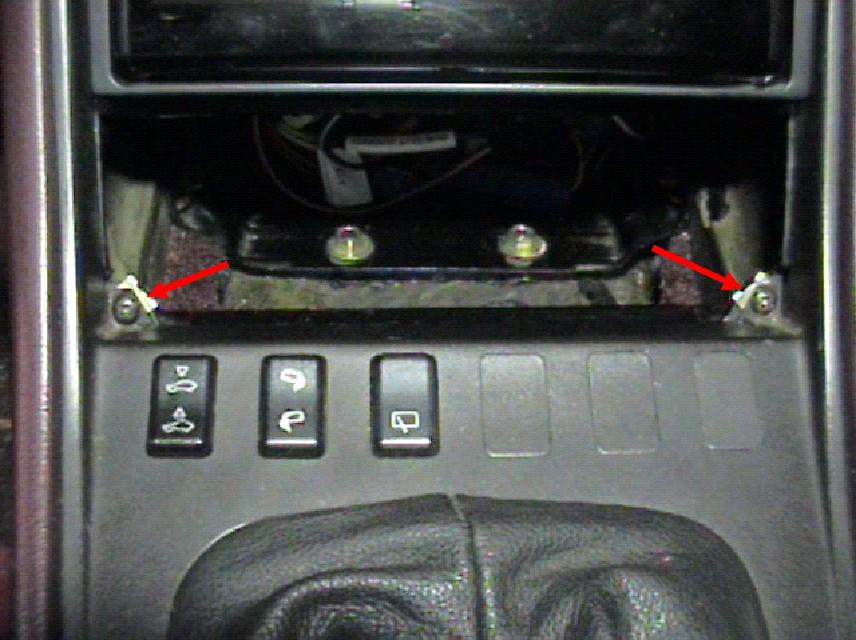
Removing the Late Sunroof Console Switch for Testing / Replacement

  1. Disconnect the sunroof switch plug as follows:
    1. Remove the storage pocket underneath the radio. This can be done by sliding both hands into the pocket, and pressing outward on the sides of the pocket with your hands while pulling the pocket straight out of the console. This will expose two Phillips head screws which you'll need to remove.


    2. Remove the ash tray from the center console by pulling it straight up out of the console and remove the two Phillips head screws at the back of the console.

    3. Lift up on the console insert. You may have to remove the trim piece from around the radio to remove the console insert.
    4. There are two plastic tabs on either side of the console switch which must be released to remove the switch. Use extreme caution when releasing these tabs as they can easily be broken. Nothing will make you more angry than having to replace a perfectly good switch because you've broken off the tabs. The way I release the tabs is to slide small flat tip screwdrivers under both tabs on both sides simultaneously. This releases all four tabs at the same time and the plug should slide off the switch easily.


  2. The console switch can be tested while it is still in the console insert. However, if you desire to remove and test it or if the switch has been tested and determined to be faulty, remove it as follows:

    1. There is a tab on either side of the console switch that holds it into the console insert. Use extreme caution when removing any console switch as the retaining tabs are easily broken.

    2. Insert a small flat tip screwdriver into the opening on the console insert to depress the tab on the switch while gently pulling outward on the switch.

    3. Often the switch will come out by just releasing the tab on one side of the switch and swinging it out of the holder. However, if you feel any resistance, depress the tab on the other side of the switch to release it and slide it out of the holder.
    4. When re-installing the switch or installing a new switch, slide it straight into the holder on the back of the console insert.

Console Switch Testing

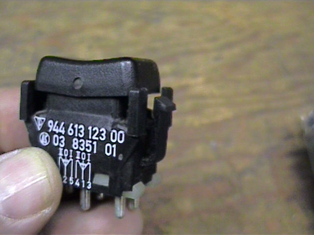
The pictures shown for this section are for an early 944 sunroof system console switch. However, the function and switch terminal labelling is identical for the late model sunroof system console switch.


When the sunroof switch is depressed in the BACK (A) direction, the resistance readings between terminals 2-5 and terminals 1-3 on the console switch should be less than 1 ohm. When the switch is depressed it the FORWARD (B) direction, the resistance readings between terminals 2-6 and terminals 2-4 should be less than 1 ohm. If the proper readings are obtained, the sunroof switch is good.

Directional Relay Testing

If one or both of the sunroof directional relays is bad, the sunroof will typically not operate in any direction. However, it is possible for the sunroof to operate in one direction and not the other with one bad directional relay. Therefore, when testing the directional relays, it's a good idea to test both relays at the same time.

Sunroof Directional Relays

Testing

  1. Remove both sunroof directional relays from the terminal block near the sunroof motor (see picture above). The relays can be difficult to remove and it may be necessary to pry gently with a small flat tip screwdriver along the bottom edge of the relay to free it from the terminal block. If so, use extreme caution when trying to pry up the relay as the terminal (87) closest to the outside of the car (later sunroof systems) on each relay will always have 12 VDC present.

    NOTE

    The directional relay terminals should be clearly labelled on the bottom of the relay.

  2. Connect an ohmmeter between terminals 30 and 87a on the relay. The resistance read across those terminals should be less than 1 ohm.
  3. Connect a DC voltage source to the relay (a 9V battery is normally sufficient) with the DC positive lead connected to terminal 85 of the relay and the DC negative lead connected to terminal 86. You should hear an audible click from the relay. The resistance now read across terminals 30 and 87a of the relay should be ∞.
  4. Move the ohmmeter lead from terminal 87a to terminal 87 of the relay. The resistance should read less than 1 ohm.
  5. Disconnect the DC voltage source from the relay. You should again hear an audible click. The resistance between terminals 30 and 87 should now read ∞.
  6. If all of the resistance checks on the relay are good, the relay is functioning normally.

While checking the directional relays, it's also a good idea to check that the voltage supply to the relay terminal block is good and that the wiring connections from the relay block to ground are good. These insure checks ensure that the relay will function properly provided it gets a signal from the sunroof switch to actuate.

On early 944 sunroof systems, install the ignition key into the ignition (not required on later sunroof cars). With a multimeter, you should read 12 VDC on both terminal 87s to ground and less than 1 ohm resistance between the 86 terminals to ground and 87a terminals to ground. If the voltage reading on the 87 terminals is bad, check the following:

Sunroof Motor Testing

Testing the sunroof motor is only necessary if the sunroof motor will not run and all of the other associated tests are satisfactory. To test the sunroof motor simply disconnect the sunroof motor plug connector and connect an external 12 VDC voltage supply.

Ignition Switch Testing

If the main sunroof relay does not test satisfactorily, it may be due to a faulty power supply to the the relay. This is most likely due to a faulty ignition switch or wiring between the ignition switch and relay.

Ignition Switch - Early Sunroof Cars

  1. Insert the key into the ignition switch.
  2. Check for approximately 12 VDC at terminals "A" and "R" on the main sunroof relay socket.
  3. Turn the ignition switch to the ON position and check for approximately 12 VDC at terminal 15 on the sunroof relay socket.
Ignition Switch - Late Sunroof Cars

  1. Turn the ignition switch to the ACCESSORY position.
  2. Check for approximately 12 VDC at terminals "A" and "R" on the main sunroof relay socket.
  3. Turn the ignition switch to the ON position and check for approximately 12 VDC at terminal 15 on the sunroof relay socket.

Clark's Garage © 1998