ELECT-19, Sensors and Gauges - Information, Troubleshooting, and Testing


Acrobat Printable Version

CONTENTS

Coolant Temperature Gauge

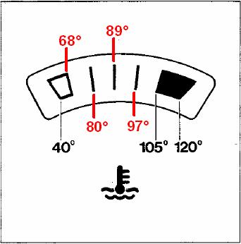
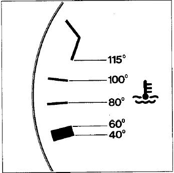
There are two different styles of coolant temperature gauges used on 924s and 944s. The early style gauge was used on all models of 924s and on 944s up to the 1985 model year. The later gauge was installed on 1985.5 and newer 944s and 968s.

One of the difficult things about using a 924/944/968 coolant temperature gauge is that there are no real temperatures indicated on the gauge face. This can make it difficult to determine if the gauge, cooling system, or cooling fans are operating properly. It is therefore help to know what temperatures correspond to the markings on the gauge face. The diagrams below show those relationships. Temperatures are shown in degrees Celsius.

Many times I hear folks ask "what the normal coolant temperature for a 944?" Well, it's a difficult question to answer because there are a number of factors which can effect coolant temperature. However, generally speaking, in cool to moderate climates (up to about 25 °C) driving on the highway, 944 coolant temperatures will normally run between 80-90 °C. Under these conditions, the system typically runs cool enough that the radiator cooling fans will not run.

In warmer climates (25-35 °C) and in heavy traffic conditions with stop and go driving, coolant temperatures may run as high as 100 °C. The cooling fan(s) should come on at approximately 92 °C to reduce coolant temperature. If your coolant temperature consistently runs higher than 100 °C, it's time to start looking for problems. Realize that the problem could be an actual high temperature problem or it could be a problem with the temperature sensor or gauge.

Time and time again, I hear folks complaining about the car's coolant temperature running significantly higher than normal. When I start talking to them, I frequently find that these symptoms occur after a round of performance modifications where they've increased the horsepower the engine is making. What is frequently overlooked is that when an engine makes more horsepower, it makes more heat and more heat is rejected to the cooling system. Since nothing has been done to increase the capacity of the cooling system, with the increase heat load the steady-state cooling temperatures are naturally going to run higher than before. This means that the cooling fans will run more frequently, run longer, and have a harder time reducing/maintaining coolant temperature in hot weather and in stop and go driving. Realize also that this also means higher steady-state oil temperatures, lower oil viscosity, and hence lower than normal steady-state oil pressures.

Coolant Temperature Gauges

Early 944 (Pre-1985.5), 924
Late 944 (1985.5 and Newer)
The numbers in red on the early gauge were determined by FR Wilk through interpolating the Bosch sender curves.

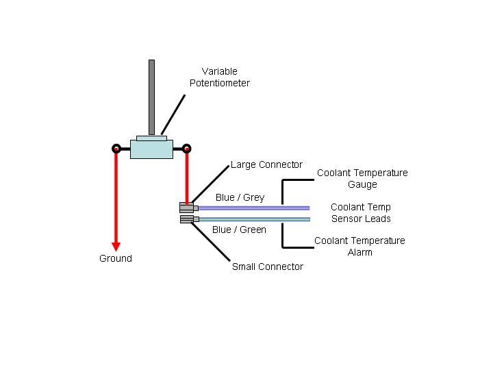
Testing Coolant Temperature Gauges

Tools

Procedure

  1. Disconnect the two spade connector leads from the temperature gauge sensor.

  2. Using the appropriate table below, set the variable potentiometer to one of the resistances listed.

    Early 944s (pre-1985.5), 924
    Temperature (°C)
    Resistance (Ohms)
    40
    287.4
    105
    33.6
    120
    22.7

    Late 944s (1985.5 and Newer)
    Temperature (°C)
    Resistance (Ohms)
    40
    287.4
    60
    134.0
    80
    69.1
    100
    38.5
    115
    25.8

  3. Connect the larger of the disconnected sensor leads to one terminal of the variable potentiometer being careful not to change the potentiometer setting. Connect the other terminal of the variable potentiometer to a grounding point in the engine compartment.

  4. Turn the ignition switch to the ON position.
  5. Check the temperature gauge reading compared to the required indication for the resistance on the variable potentiometer.
  6. Repeat as necessary for all temperature-resistance combinations in the table.
  7. If the gauge appears to be reading normally and you still suspect that the temperature readings are abnormal during engine operation, proceed to the temperature sensor testing procedure.
  8. If you determine that the gauge is bad, replace it or send it to an authorized VDO repair facility for service.

Testing Oil Pressure Gauge

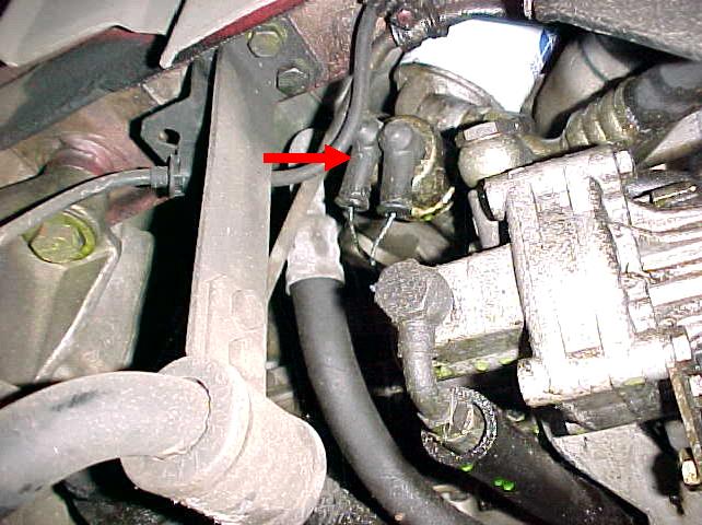
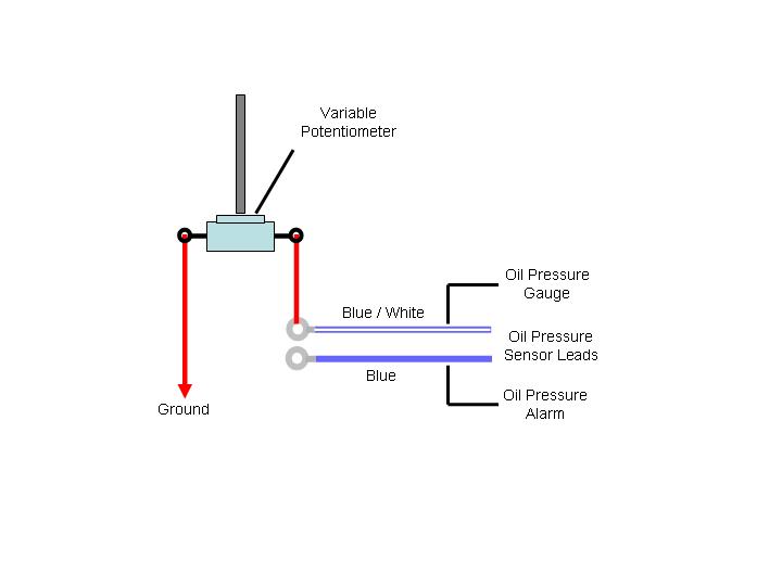
Problems with the oil pressure indication are commonly caused by a failing oil pressure sending unit. Normally, at startup when the ignition switch is turned on, the oil pressure will indicate 5 bar. Upon starting the engine the oil pressure should indicate between 4.5 - 5 bar. As the engine heats up the oil pressure will gradually decrease until the oil reaches normal operating temperature. At that point the oil pressure will normally indicate around 2.5 - 3 bar. On very hot days the oil pressure could indicate as low as 2 bar. If the indication falls below 2 bar and remains consistently below 2 bar, it could indicate a problem with the main or rod bearings.

Oil Pressure Gauge Testing

  1. Disconnect the leads from the oil pressure sending unit.

  2. Using the multimeter and the variable potentiometer, set the potentiometer to one of the resistances listed in the appropriate table below for your vehicle.

    1982-85 944
    Oil Pressure (Bar)
    Resistance (Ohms)
    0
    10.0
    3
    116.0
    5
    184.0

    1985.5 and Newer 944
    Oil Pressure (Bar)
    Resistance (Ohms)
    1
    29.6
    2
    65.3
    3
    98.9
    4
    133.6
    5
    184.0

  3. Connect the oil pressure sending unit lead which was removed from terminal "G" on sensor to one leg of the variable potentiometer. Connect the other leg of the variable potentiometer to a grounding point in the engine compartment.

  4. Turn the ignition switch to the ON position.
  5. Check the oil pressure gauge reading compared to the required indication for the resistance on the variable potentiometer.
  6. Repeat as necessary for all oil pressure-resistance combinations in the table.
  7. If the gauge appears to be reading normally during testing and abnormally during engine operation, there may be a problem with the oil pressure sending unit. If you don't have the resources to fabricate connections to apply an external pressure source to the sending unit, it may be necessary to simply replace the sending unit without testing.

Testing Fuel Level Gauge

Testing and repair for the fuel level indication is covered in ELECT-18, Fuel Level Indication Problems / Repairs.

Air Flow Sensor (AFM) Testing

The Air Flow Meter (AFM) testing section has been move to a stand-alone procedure which is more accurate and now includes instructions for cleaning and repairing erratic operation. For AFM testing, refer to ELECT-22.

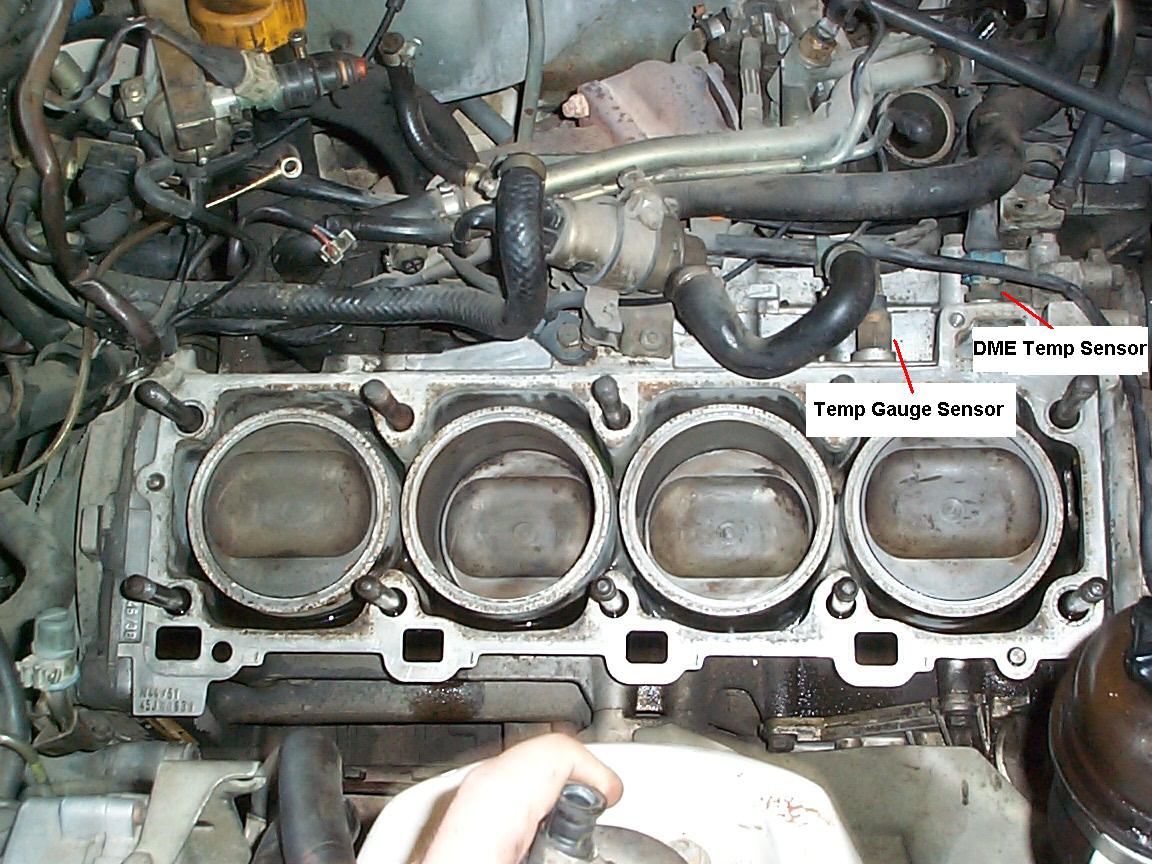
DME Temperature Sensor Testing

Tools

Procedure

  1. Turn the ignition switch OFF.
  2. Disconnect the DME computer electrical connector.
  3. Connect an ohmmeter between terminal 13 on the disconnected DME plug and ground.
  4. Check for the following resistances:

    DME Temperature Sensor Resistances
    15-30 °C (59-86 °F)
    At 59 °F approximately 3.3 k-ohms
    At 86 °F approximately 1.46 k-ohms

    NOTE

    The next part of the DME temperature sensor testing assumes that the temperature gauge on the dash is working properly.

  5. Connect the DME plug connector.
  6. Start the car and run until the temperature gauge on the dash indicates approximately 80 °C (see dash temperature gauge section). If you suspect that the dash gauge is not working properly, you can check the surface temperature on the block near the DME temperature sensor.
  7. Turn the engine OFF.
  8. Disconnect the DME computer plug and connect ohmmeter as described in Step 3.
  9. Turn the ignition switch back ON (Do Not Attempt to Start Car) and check dash indication is still reading 80 °C. Alternatively, check the surface temperature on the block near the DME temperature sensor. Compare resistance to the value in the table below.

    DME Temperature Sensor Resistances
    80 °C (176 °F)
    280-360 ohms

  10. If the resistances don't meet the tolerances listed, the DME Temperature sensor should be replaced. If the resistances indicate higher than the specs, it will cause a richer mixture. Lower resistances than the specs will result in a lean mixture.

Throttle Position Switch Testing

Throttle Position Switch testing is covered in FUEL-06, Throttle Position Switch Information, Troubleshooting, Replacement, and Adjustment.

Speed and Reference Sensor Testing

Speed and Reference sensor testing is covered in IGN-02, Checking, Replacement, and Adjustment.

Oxygen Sensor Testing

Tools

Procedure

  1. Start the car and run until engine is at normal operating temperature.
  2. Disconnect the O2 sensor and connect a voltmeter to the sensor plug.
  3. Run the engine at approximately 2500 rpm.
  4. Introduce propane into the intake to enrich the mixture until the engine rpm drops by 200 rpm. You may be able to create the same affect by disconnecting the vacuum line to the fuel pressure regulator. However, you'll have to plug the vacuum line to prevent a vacuum leak to the intake manifold.
  5. If the voltmeter reading rapidly rises to greater than 0.9 VDC the O2 is correctly indicating a rich mixture. If the voltmeter response is sluggish or the voltage remains below 0.8 VDC, the sensor should be replaced.
  6. Secure the propane addition.
  7. While continuing to run the engine at 2500 rpm, disconnect a vacuum line from the intake to cause a lean mixture.
  8. If the voltmeter indication rapidly drops to less than 0.2 VDC, the O2 sensor is properly reading a lean mixture. If the voltmeter indication responds sluggishly or remains above 0.2 VDC, replace the sensor.

Clark's Garage © 1998