LUBE-01, Oil Cooler General Information and Seal Replacement
Acrobat Printable Version
Introduction
The first indication of failing oil cooler seals are normally a "milkshake" looking mixture in the coolant tank. This can also be indicated by a failing head gasket. However, most of the time it's the oil cooler seals. The seals must be replaced immediately at the first indication of seal failure. Oil in the coolant isn't all that critical although the cleanup can be messy. However, eventually the coolant will make its way into the oil system and the results will most likely be catastrophic.
I'd like to thank Heinrich Smit for providing the oil cooler pictures I'm using it this procedure.
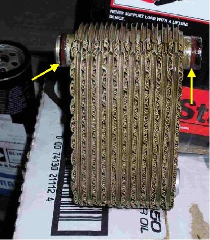
* Normally aspirated cars use two o-rings while turbocharged cars use one o-ring. The older style of this o-ring was red in color. It has been replaced by a new style o-ring which is green in color bearing the part number 999 707 040 40.
Tools
Metric Socket Set
Metric Combination Wrench Set
Thin Head 24mm (or 15/16") Open End Wrench
Alignment Tool 9262/1 (for cars using oil pressure relief valve 944 107 035 02 is used)*
Alignment Tool 9215 (for cars using oil pressure relief valve 944 107 035 11 is used)*
* See Oil Pressure Relief Valve Information Procedure to determine which relief valve you have.
Procedure
Place the vehicle on jack stands.
Remove the belly pan.
Disconnect the exhaust headers (13mm socket and ratchet and 13 mm combination wrench) and move them back out of the way. Although it does simplify matters, they do not have to be removed completely from the vehicle.
Remove the oil filter.
Disconnect the wires from the oil pressure sending unit.
Using the thin head 24mm open end wrench, remove the oil pressure sending unit.
Remove the oil pressure relief valve.
If your vehicle has an external oil cooler disconnect the oil cooler supply and return lines from the oil cooler housing.
Using COOL-02, drain the coolant from the vehicle.
Using a 10mm socket and ratchet or 10mm combination wrench remove the heat shield above the oil cooler housing.
NOTE
You may find it necessary to remove the power steering pump. Remove the pump from the mounting bracket, leave the lines connected, and hang the pump out of the way.
Using a 13mm socket and ratchet or 13mm combination wrench, remove the bolts for the oil cooler housing.
Remove the oil cooler housing and the cooler element (for cars with integral oil cooler).
When you remove the cooler and housing, the seals may remain attached to the cooler housing or to the block mating surface.
NOTE
There are actually two different styles of seal arrangement. In some cases you find three separate seals. However, you may also find a single gasket that has all three seals build in as an integral part of the gasket. The arrows in the picture above show the location of the three seals. The arrangement with three separate seals is the old style arrangement and has been replaced by a single integral seal.
Remove all of the old seals from the cooler housing, block, and cooler element.
On normally aspirated cars, replace the two o-ring seals on both nozzles for the cooler (999 707 043 40).
On normally aspirated cars, install the plastic washer (944 107 154 00) between the cooler element and cooler housing and slide the element into the housing.
OIL COOLER ASSEMBLY
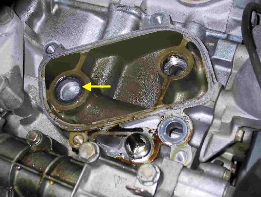
Lay a straight edge across the top of the cooler housing next to the cooler element guide boss and determine the distance between the lip of the boss on the cooler element (see picture below) and the straight edge. The distance should be 0 +/- 0.25 mm. Do NOT install the cooler housing gasket before taking the measurement. Install shims (944 107 219 00) as necessary to obtain the required measurement. Shim thickness is 0.5 mm. Normally no more than one shim is required.
On normally aspirated cars, replace the cooler element rubber mount (944 107 153 02) in the groove on the block. Apply a coat of light grease to the ring to hold it in place on the block during assembly.
On normally aspirated and turbocharged cars, install a new gasket (944 107 147 03) on the block. Some gasket sets are still showing up with three separate seals instead of one integral gasket. In either case, use a coat of light grease to hold the gasket/seals in place while mounting the cooler assembly.
On turbocharged cars install a new o-ring on the connector pipe for the oil filter/thermostat housing (999 707 043 40).
Bolt the assembled oil cooler (or filter housing on turbocharged cars) to the block. Do not fully tighten mounting bolts yet.
Determine the correct oil pressure relief alignment tool. (See TOOLS above and Oil Pressure Relief Information procedure).
Insert the tool into the vacant opening for the oil pressure relief valve to align the housing.
Torque the oil cooler housing bolts (M8) to 20 Nm (15 ft-lbs).
Remove the alignment tool and install the oil pressure relief valve. Torque the relief valve to 45 Nm (33 ft-lbs).
Install the oil pressure sending unit and tighten to 35 Nm (26 ft-lbs).
Reconnect the electrical wires for the oil pressure sending unit.
Install the heat shield above the oil cooler housing. Torque the heat shield bolts (M6) to 8 Nm (6 ft-lbs).
Apply a light coat of oil to the seal of a new oil filter and install filter. Tighten filter to 20 Nm (15 ft-lbs).
Install the exhaust headers.
If the cooler seal failure was evidenced by a "milkshake" solution in the coolant reservoir, flush the cooling system thoroughly. After flushing, fill and vent the cooling system using COOL-02.
If there is reason to believe that coolant may have entered the oil system, change the oil, run the engine until it is warm, then, change the oil and install a new filter.
Install belly pan and remove vehicle from jack stands.