Acrobat Printable Version
|
SUSP-06, Torsion Bars - Removing, Replacing, and Indexing
|
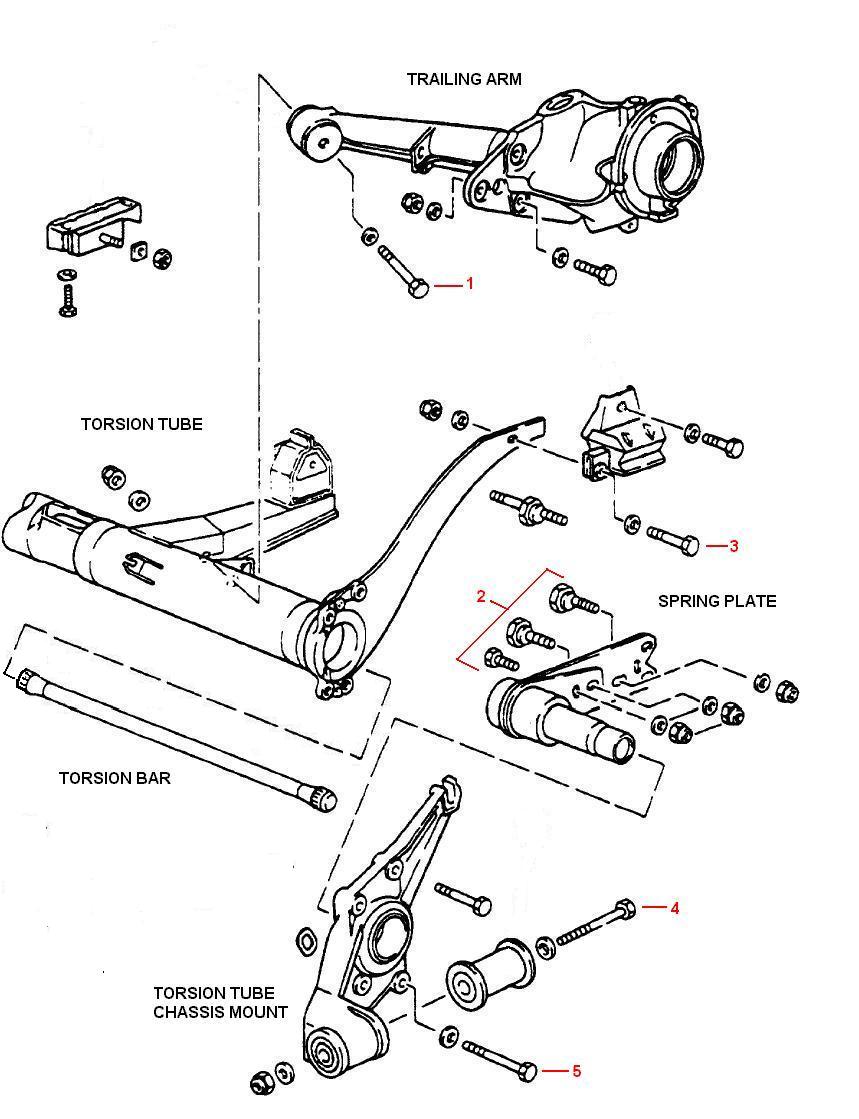
Replacing the torsion bar on a 944 is not all that difficult. However, reindexing the torsion after completion is a pain and can be very time consuming. There are a couple of reasons for removing the torsion bars. The first is to make a ride height adjustment and the second is to upgrade to a stiffer torsion bar. I was fortunate enough to come across a very good torsion bar replacement procedure written by Marc Belanger to use as a guide. The following procedure is based on my own experience and the shared experiences of Marc, Doug Donsbach, and others. These combined experiences should provide you with a pretty clear picture of what it takes to remove, replace, and reindex the torsion bars in your car. I'll also be adding some pictures to help guide you along the way. Refer to the diagram below for location of the major components and fasteners for the rear suspension.
First off, if you think you need to make a change in ride height, you first need to take a ride height measurement and determine how much of a change is needed. Typically, the best place to take a ride height measurement is from the ground up to the top-center of the fender well (i.e. centered on the wheel). A good number to use for ride height measurement at that point is about 25 inches (63,5 cm). It's really not a great idea to go much lower than that. And, you'll achieve the best results if you keep the same ride height front-to-rear. If you determine that a change in ride height is in order, a small amount of adjustment is available via the eccentric bolt on the trailing arm spring plate. The amount of adjustment available depends on where the eccentric is set to begin with. The total adjustment range is approximately 1 inch (2,5 cm). Assuming the eccentric is centered (seldom the case), you'll only be able to raise or lower the ride height by about 1/2 inch.
Tools
Other Procedures Needed
You should have already determined the pre-existing ride height as described in the introduction section.
If you are simply reindexing existing torsion bars, proceed to Step 6. Steps 1-5 are only required when installing different torsion bars.


Replacing

If you are replacing a solid torsion bar with a hollow torsion bar, the manufacturer should supply a solid diameter that the hollow bar is equivalent to. Use the solid bar equivalent diameter in the calculation below.
Example:Let's assume you currently have 25.5mm torsion bars and want to swap to 30mm bars and that the loaded-to-unloaded range on your old bar is 50mm. The loaded-to-unloaded range for your new bar would be calculated as follows:

Indexing the torsion bars on a 944 is tedious at best, but fortunately it isn't rocket science. However, after the following explanation of how torsion bar indexing works it may seem like rocket science.
If you've never studied geometry, this may completely new to you. However, bear with me and we will ultimately arrive at some formulas you will be able to use regardless of whether you understand circular geometry. First, we have to understand that in geometry a circle is divided into increments called degrees (°) and that there are 360 degrees in a complete circle. Each degree is divided into increments called minutes and there are 60 minutes (') in each degree.
Now, if you examine a 944 torsion bar, you'll find that the inner end of the torsion bar has 40 splines and the outer end of the bar has 44 splines. So, if we take the number of degrees in a circle and divide it by the number of splines, will find the amount of rotation that can be obtained by moving the bar 1 spline.
For the inner torsion bar end:
For the outer torsion bar end:
The measured length of the trailing arm on a 944 is 16.5" from the center of the torsion bar out to the center of the hub. Since we now know the length of the trailing arm and the number of degrees of rotation for each tooth of spline movement, we can now use fairly simple geometry for right triangles to calculate the change in ride height with each change in spline position.

Using the formulas for right triangles below, we can calculate the change in ride height (X1).
Where:
A = Length of Side adjacent to angle theta (θ)So, for the inner tie rod spline movement we get:O = Length of Side opposite angle
H = Length of the Hypotenuse
Now for the part that may be a little harder to follow. This calculation is based on the assumption that we are dealing with a perfect right triangle. And, if you've ever studied geometry, you'll remember that the longest side of a right triangle is the hypotenuse. In our case with the trailing arm, the hypotenuse is simply the trailing arm moved from one position to another. Since the change in ride height calculation is based on the end of the trailing arm dropping straight down at a right angle from it's original position, our calculation is somewhat flawed. In reality, the hub end of the trailing arm swings along the arc of a circle. For it to drop straight down at a right angle from it's original position, the trailing arm would have to change length and we know that isn't possible. Unless, if course, Porsche comes up with something similar to Variocam for the suspension system. Anyway, we can still use the right triangle rules to come up with the actual ride height change if we do a few more calculations.
If we calculate the length of the hypotenuse at any given angle theta, that will give us the theoretical length that the trailing arm would have to lengthen to in order to maintain our right triangle. Then, we can use the difference between the theoretical trailing arm length and the actual length to form a new (smaller) right triangle which will allow us to determine the error introduced into our original calculation. I know that's hard to visualize but, bear with me.
So, let's first calculate the length of the hypotenuse (X2) given that angle θ = 9° or one tooth on the inner torsion bar spline:

If we take the difference between the hypotenuse length at angle θ and the actual trailing arm length, we obtain a length (X3) which we can use as the hypotenuse of a new (smaller) triangle.

And finally, we can calculate the actual change in ride height (X5) for inner spline movement by subtracting the error (X4) from the original ride height change (X1):
This is approximately 6.6 cm of change in ride height. Using the same calculations and substituting in 8.18° for angle θ, we obtain the actual ride height change for a single spline rotation on the outer torsion bar splines.
That's roughly 6 cm.
Now that we know just how much or a change in ride will occur per spline on each end of the torsion bar, let's take a look at a specific example. Assume we're standing beside the driver's side of the car looking at the torsion bar end and spring plate (see picture below).
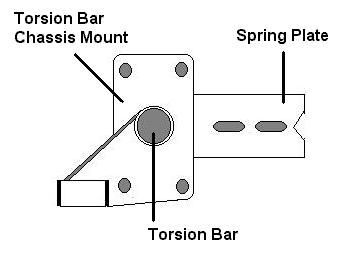
If we leave the spring plate and chassis mount attached to the outer end of the torsion bar and rotate the inner end of the bar one spline in the counter-clockwise direction, it will raise the end of the spring plate. This will lower the ride height of the car by 2.58". Then if we leave the inner end fixed in the torsion tube and rotate the spring plate and chassis mount one spline in the clockwise direction it will lower the end of the spring plate and raise the ride height of the car by 2.35". The net result will be that the car is 0.23" lower (or approximately 6mm).
Clark's Garage © 1998


