ENG-06, Camshaft (Timing) Belt and Balance Shaft Belt Installation


Acrobat Printable Version

Tools

Other Procedures Needed

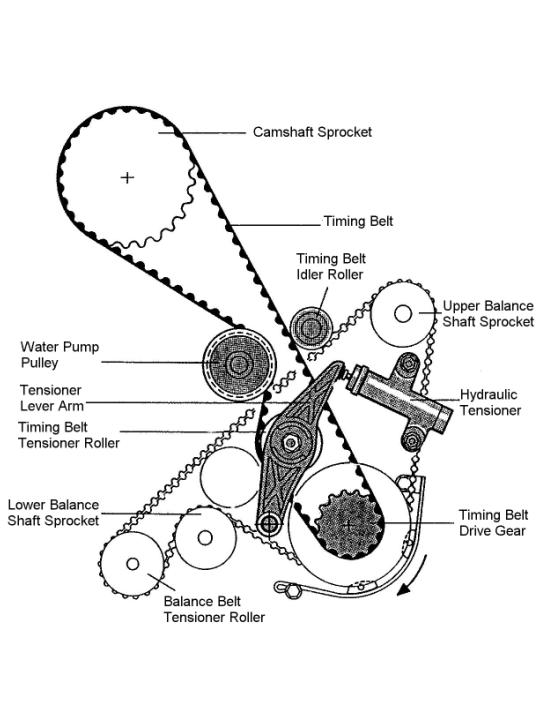
Refer to the Timing and Balance Shaft Belt Drawings for details:

Camshaft Belt Installation

  1. Install the rear timing cover if removed.
  2. Install the water pump idler roller if removed. Tighten the idler roller retaining bolt to 45 Nm (33 ft-lbs).
  3. Install crankshaft gear, if removed, ensuring that the lip on the timing gear is oriented toward the front of the car.
  4. Install the camshaft sprocket if removed.
  5. Install the cam belt tensioning roller if removed.

    NOTE

    On cars with spring tensioners, I prefer to install the spring tensioner as I'm routing the timing belt. In fact, I always remove the spring tensioner to install a new timing belt as it is much easier to route the belt.

  6. If flywheel lock was not used verify crankshaft at TDC on cylinder number 1 (ENG-13).
  7. Align mark on camshaft sprocket with mark on rear distributor housing.
  8. Install timing belt as follows:
    1. Place belt on crankshaft gear.
    2. Route belt around camshaft sprocket. Insure that there is no slack in the belt between cam sprocket and crankshaft gear. Also, make sure that neither the crankshaft or the cam sprocket move from TDC during the belt installation.
    3. Finish by routing the belt around the water pump pulley and tensioning roller.
  9. Tension the camshaft belt using ENG-10.

Balance Belt Installation

  1. If removed, install the balance belt sprockets using ENG-08.
  2. Using ENG-13, set the crankshaft to TDC for cylinder number 1.
  3. Install the balance belt gear on the crankshaft if removed.
  4. If the crankshaft bolt was removed, perform the following:
    1. Using ENG-03, Install the flywheel lock.
    2. Ensure the crankshaft timing gear, balance shaft belt gear, and alternator/AC compressor pulley are installed.
    3. Install the crankshaft bolt and torque to 210 Nm or 155 ft-lbs.
    4. If equipped, install the power steering pulley. Tension the pulley mounting bolts to 13 Nm (9.5 ft-lbs).
    5. Remove the flywheel lock.
  5. Align the upper balance shaft so that the notch on the edge of the sprocket aligns with the notch in the rear timing cover. It is located at approximately the 1 o'clock position.
  6. Align the lower balance shaft so that the notch on the edge of the sprocket aligns with the raised tab which is molded into the rear timing cover. It is located at approximately the 7 o'clock position.
  7. Install the balance belt as follows:
    1. Route the balance belt from the upper balance sprocket around the crankshaft gear. Ensure there is no slack in the belt from the upper sprocket to the crankshaft gear.
    2. Continue routing the belt around the lower balance sprocket again ensuring there is no slack from the crankshaft sprocket to the lower balance sprocket.
    3. Route the belt around the tensioning roller and back to the upper balance sprocket.
    4. Pre-tension the balance shaft belt enough to remove any slackness in the belt and tighten the tensioning roller locknut.

    NOTE

    Turn the tensioning roller clockwise to tighten, counter-clockwise to loosen.

  8. Install the balance shaft sprocket covers and retaining bolts. Tighten the retaining bolts to 45 Nm (33 ft-lbs) while holding the sprocket with Special Tool 9200.
  9. Rotate crankshaft two complete turns and set at TDC for number 1 cylinder.
  10. Verify that the camshaft, balance shaft, and flywheel marks are aligned for TDC.

    NOTE

    It is not unusual for the balance shaft marks to be slightly out of alignment. Most often if they do not align, the lower shaft will be aligned with its mark and the upper shaft will be off approximately one-half tooth. If the shaft are out of alignment by a full tooth or more, they should be realigned.

  11. Tension the balance shaft belt using ENG-10.
  12. Install the front timing belt covers.
  13. Install alternator and power steering belts and retension.
  14. Install the air filter assembly (AF-01).
  15. Reconnect battery.

Clark's Garage © 1998